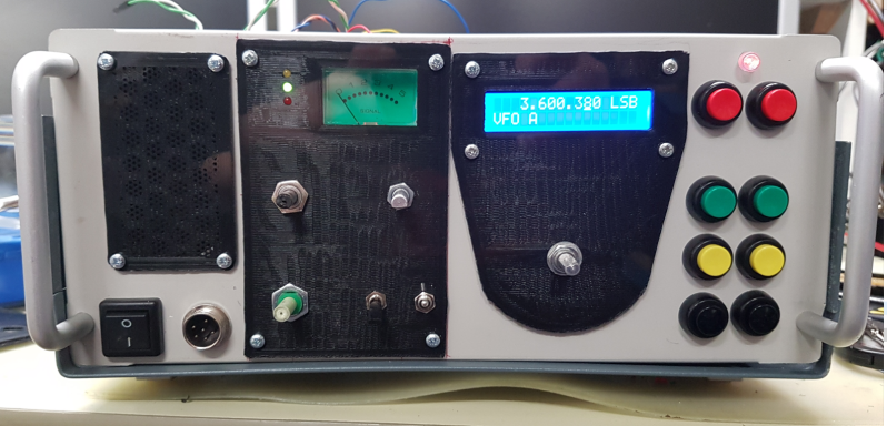
Now its getting somewhere - The panel is now in place and the left hand front handle has been found again. (Yes - forgot where I put it). The on/off switch and microphone socket are back on and connected. You can see above the two red pushbuttons the power LED. This is a two colour LED. Red for receive and Green for Transmit.
Still in place the the BZP silver screws. You can see a load of wires sticking up as the top lid has not been replaced on the case yet.

Now it is time for the switch on test.
Always a moment of hesitation and final checks of all the wiring, and for loose metal bits and all screwdrivers and allen keys are accounted for.
And there it is - all switches working and even the USB/LSB display in the top right of the LCD works, despite my efforts not to wire it up correctly.
Noticed that the S-Meter looks a bit dark - perhaps some LEDs will make that easier to see. Something to do later I think. The power LED indicating receive - Red can be seen lit up.
The LED next to the s-meter indicate the mode for the Sotabeams digital filter which is controlled by the encoder controller above the two toggle switches.
Now to get some Whizz3Dparts Tuning/Encoder and instrumentation knobs fitted.
Add comment
Comments